
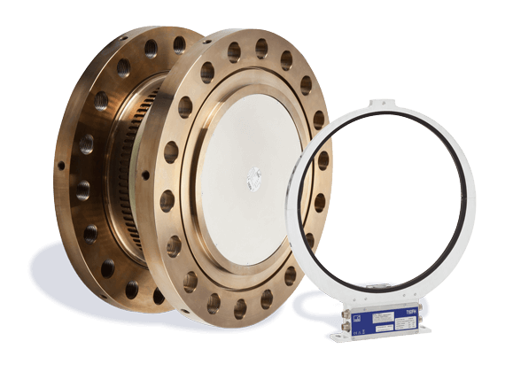
T40FM 扭矩传感器可以测量高达 80 kN·m 动态扭矩 - 高精度高可靠 – 并具有极高性价比。结实可靠,可用于恶劣环境,因此其是大型发动机和传输系统生产和测试的理想选择。带有数字和模拟接口,更容易集成到测试系统中。 其和前任 T10FM 具有相同的几何尺寸,可以进行简单替换即可进行系统升级。
| Type | T40FM | ||||||||||||||||||||
| Accuracy class | 0.1 | ||||||||||||||||||||
| Torque measuring system, frequency output | |||||||||||||||||||||
| Nominal (rated) torque Mnom | kN×m | 15 | 20 | 25 | 30 | 40 | 50 | 60 | 70 | 80 | |||||||||||
| Nominal (rated) rotational speed optional |
rpm rpm | 6000 8000 |
4000 6000 |
3000 4500 |
|||||||||||||||||
| Non‐linearity including hysteresis, related to nominal (rated) sensitivity For a max. torque in the range: between 0% of Mnom and 20% of Mnom > 20% of Mnom and 60% of Mnom > 60% of Mnom and 100% of Mnom |
% % % |
<土0.03 (optional <土0.015) <土0.065 (optional <土0.035) <土0.1 (optional <土0.05) |
|||||||||||||||||||
| Relative standard deviation of reproducibility (variability), per DIN 1319, related to the variation of the output signal |
% | <土0.05 | |||||||||||||||||||
| Temperature effect per 10 K in the nominal (rated) temperature range on the output signal, related to the actual value of the signal span on the zero signal, related to the nominal (rated) sensitivity |
% % |
<土0.1 <土0.05 |
|||||||||||||||||||
| Nominal (rated) sensitivity (span between torque = zero and nominal (rated) torque) Option SU2 Option DU2 Option HU2 Sensitivity tolerance (deviation of the actual output frequency at Mnom from the nominal (rated) sensitivity) |
kHz kHz kHz % |
5 30 120 土0.2 |
|||||||||||||||||||
| Load resistance | kΩ | >2 | |||||||||||||||||||
| Output signal at zero torque Option SU2 Option DU2 Option HU2 |
kHz kHz kHz | 10 60 240 |
|||||||||||||||||||
| Nominal (rated) output signal (RS422, 5 V symmetrical) with positive nominal (rated) torque, Option SU2 with positive nominal (rated) torque, Option DU2 with positive nominal (rated) torque, Option HU2 with negative nominal (rated) torque, Option SU2 with negative nominal (rated) torque, Option DU2 with negative nominal (rated) torque, Option HU2 |
kHz kHz kHz kHz kHz kHz | 15 90 360 5 30 120 |
|||||||||||||||||||
| Load resistance 1) | kΩ | 三2 | |||||||||||||||||||
| Long‐term drift over 48 h at reference temperature, related to nominal (rated) sensitivity Measurement frequency range (-3 dB) Option SU2 Option DU2 Option HU2 Group delay Option SU2 Option DU2 Option HU2 |
% kHz kHz kHz ms ms ms |
三0.03 1 3 6 <400 <220 <150 |
|||||||||||||||||||
| Maximum modulation range 2) Option SU2 Option DU2 Option HU2 |
kHz kHz kHz | 2.5 to17.5 15 to 105 60 to 420 |
|||||||||||||||||||
| 1) Note the necessary termination resistances as per RS-422. | |||||||||||||||||||||
| 2) Output signal range in which there is a repeatable correlation between torque and output signal. | |||||||||||||||||||||
| Torque measuring system, voltage output | |||||||||||||||||||||
| Nominal (rated) torque Mnom | kN×m | 15 | 20 | 25 | 30 | 40 | 50 | 60 | 70 | 80 | |||||||||||
| Non‐linearity including hysteresis, related to nominal (rated) sensitivity For a max. torque in the range: between 0% of Mnom and 20% of Mnom > 20% of Mnom and 60% of Mnom > 60% of Mnom and 100% of Mnom |
% % % |
<土0.03 (optional <土0.015) <土0.065 (optional <土0.035) <土0.1 (optional <土0.05) |
|||||||||||||||||||
| Relative standard deviation of reproducibility (variability), per DIN 1319, related to the variation of the output signal |
% | <土0.05 | |||||||||||||||||||
| Temperature effect per 10 K in the nominal (rated) temperature range on the output signal, related to the actual value of the signal span on the zero signal, related to the nominal (rated) sensitivity |
% % |
<土0.2 <土0.15 |
|||||||||||||||||||
| Nominal (rated) sensitivity (span between torque = zero and nominal (rated) torque) Sensitivity tolerance (deviation of the actual output frequency at Mnom from the nominal (rated) sensitivity) |
V % |
10 土0.2 |
|||||||||||||||||||
| Output signal at torque = zero | V | 0 | |||||||||||||||||||
| Nominal (rated) output signal At positive nominal (rated) torque At negative nominal (rated) torque |
V V | 10 -10 |
|||||||||||||||||||
| Load resistance | kΩ | >10 | |||||||||||||||||||
| Long‐term drift over 48 h at reference temperature, related to nominal (rated) sensitivity Measurement frequency range (-3 dB) Option SU2 Option DU2 Option HU2 |
% kHz kHz kHz |
£0.03 1 3 6 |
|||||||||||||||||||
| Residual ripple 3) | mV | < 40 (peak‐to‐peak) | |||||||||||||||||||
| Maximum modulation range 4) invalid measured value |
V V | 土12 13 to 15 |
|||||||||||||||||||
| Torque measuring system in general | |||||||||||||||||||||
| Energy supply | |||||||||||||||||||||
| Nominal (rated) supply voltage (separated extralow voltage) |
VDC | 18 to 30 | |||||||||||||||||||
| Current consumption in measuring mode in startup mode |
A A | <1 (typ. 0.3 for a 20 V supply voltage) <4 (typ. 2) for max. 50ms |
|||||||||||||||||||
| Nominal (rated) power consumption | W | <10 (typ. 6) | |||||||||||||||||||
| Maximum cable length | m | 50 | |||||||||||||||||||
| Shunt | |||||||||||||||||||||
| Tolerance of the shunt signal, related to Mnom at reference temperature | % | <土0.05 | |||||||||||||||||||
| Nominal (rated) trigger voltage | V | 5 | |||||||||||||||||||
| Trigger voltage limit | V | 36 | |||||||||||||||||||
| Shunt signal on | V | >2.5 | |||||||||||||||||||
| Shunt signal off | V | <0.7 | |||||||||||||||||||
| 3) Signal frequency range 0.1 to 10 kHz. | |||||||||||||||||||||
| 4) Output signal range in which there is a repeatable correlation between torque and output signal. | |||||||||||||||||||||
| Rotational speed measuring system | |||||||||||||||||||||
| Nominal (rated) torque Mnom | kN×m | 15 | 20 | 25 | 30 | 40 | 50 | 60 | 70 | 80 | |||||||||||
| Measurement system | Magnetic, via AMR sensor (Anisotropic Resistive Effect) and magnetized plastic ring with embedded steel ring | ||||||||||||||||||||
| Magnetic poles | 158 | 186 | 204 | ||||||||||||||||||
| Maximum positional variation of the poles | 土50 angular seconds | ||||||||||||||||||||
| Output signal | V | 5 V symmetrical (RS-422); 2 square wave signals approx. 90° phase shifted |
|||||||||||||||||||
| Pulses per revolution | 1024 | ||||||||||||||||||||
| Minimum rotational speed for sufficient pulse stability | rpm | 0 | |||||||||||||||||||
| Pulse tolerance 5) | degrees | <土0.05 | |||||||||||||||||||
| Maximum permissible output frequency | kHz | 420 | |||||||||||||||||||
| Group delay | ms | <150 | |||||||||||||||||||
| Radial nominal (rated) distance between sensor head and magnetic ring (mechanical distance) | mm | 1.6 | |||||||||||||||||||
| Working distance range between sensor head and magnetic ring 6) | mm | 0.4 to 2.5 | |||||||||||||||||||
| Max. permissible axial displacement of the rotor to the stator 7) | mm | 土1.5 | |||||||||||||||||||
| Hysteresis of direction of rotation reversal in the case of relative vibrations between rotor and stator Torsional vibration of the rotor Horizontal stator vibration displacement |
degrees mm | <approx. 0.2 <approx. 0.5 |
|||||||||||||||||||
| Load resistance 8) | kΩ | ³2 | |||||||||||||||||||
| Reference signal measuring system (0 index) | |||||||||||||||||||||
| Measurement system | Magnetic, with Hall sensor and magnet | ||||||||||||||||||||
| Output signal | V | 5 V symmetrical (RS 422) | |||||||||||||||||||
| Pulses per revolution | 1 | ||||||||||||||||||||
| Minimum rotational speed for sufficient pulse stability | rpm | 2 | |||||||||||||||||||
| Pulse width, approx. | degrees | 0.088 | |||||||||||||||||||
| Pulse tolerance 5) | degrees | <土0.05 | |||||||||||||||||||
| Group delay | ms | <150 | |||||||||||||||||||
| Axial nominal (rated) distance between sensor head and magnetic ring (mechanical distance) | mm | 2.0 | |||||||||||||||||||
| Working distance range between sensor head and magnetic ring | mm | 0.4 to 2.5 | |||||||||||||||||||
| Max. permissible axial displacement of rotor to stator 7) | mm | 土1.5 | |||||||||||||||||||
| 5) At nominal (rated) conditions. | |||||||||||||||||||||
| 6) The pulse tolerance improves with reduced distance and vice versa. | |||||||||||||||||||||
| 7) The data refers only to a central axial alignment. Deviations lead to a change in pulse tolerance. | |||||||||||||||||||||
| 8) Note the necessary termination resistances as per RS-422. | |||||||||||||||||||||
| General information | |||||||||||||||||||||
| EMC Emission (per FCC 47, Part 15, sub part C) Emission (per EN 61326-1, Section 7) RFI field strength |
- - |
Class B | |||||||||||||||||||
| Immunity from interference, as per EN61326-1, EN61326-2-3 Electromagnetic field (AM) Magnetic field Electrostatic discharge (ESD) Contact discharge Air discharge Fast transients (burst) Impulse voltages (surge) Conducted interference (AM) |
V/m A/m kV kV kV kV V |
10 100 4 8 1 1 10 |
|||||||||||||||||||
| Degree of protection, as per EN 60 529 (rotor/stator) |
- | IP54 | |||||||||||||||||||
| Reference temperature | °C | 23 | |||||||||||||||||||
| Nominal (rated) temperature range | °C | +10 to +70 | |||||||||||||||||||
| Operating temperature range 9) | °C | -20 to +85 | |||||||||||||||||||
| Storage temperature range | °C | -40 to +85 | |||||||||||||||||||
| Permissible ambient humidity Relative humidity / no condensation |
% | 5 to 95 | |||||||||||||||||||
| Mechanical shock, as per EN 60068-2-72 10) Number Duration Acceleration (half sine) |
n ms m/s2 | 1000 3 650 |
|||||||||||||||||||
| Vibrational stress in 3 directions, as per EN 60068-2-6 10) Frequency range Duration Acceleration (amplitude) |
Hz h m/s2 |
10 to 2000 2.5 200 |
|||||||||||||||||||
| Load limits 11) | |||||||||||||||||||||
| Nominal (rated) torque Mnom | kN×m | 15 | 20 | 25 | 30 | 40 | 50 | 60 | 70 | 80 | |||||||||||
| Limit torque | kN×m | 32 | 60 | 110 | |||||||||||||||||
| Max. limit load of measuring body 12) | kN×m | 100 | 200 | 350 | |||||||||||||||||
| Breaking torque (static) | kN×m | >100 | >200 | >350 | |||||||||||||||||
| Longitudinal limit force (static) | kN | 60 | 120 | 240 | |||||||||||||||||
| Lateral limit force (static) | kN | 80 | 160 | 240 | |||||||||||||||||
| Limit bending moment (static) | N×m | 6000 | 12000 | 24000 | |||||||||||||||||
| Oscillation width, per DIN 50100 (peak‐to‐peak) 13) | kN×m | 30 | 32 | 60 | 100 | ||||||||||||||||
| Mechanical values | ||||||||||||||||||||
| Nominal (rated) torque Mnom | kN×m | 15 | 20 | 25 | 30 | 40 | 50 | 60 | 70 | 80 | ||||||||||
| Torsional stiffness cT | kN×m/rad | 32050 | 63260 | 106200 | ||||||||||||||||
| Torsion angle at Mnom | degrees | 0.027 | 0.036 | 0.045 | 0.027 | 0.036 | 0.045 | 0.033 | 0.038 | 0.043 | ||||||||||
| Stiffness in the axial direction ca | kN/mm | 1380 | 1710 | 2280 | ||||||||||||||||
| Stiffness in the radial direction cr | kN/mm | 3900 | 5080 | 6170 | ||||||||||||||||
| Stiffness during the bending moment round a radial axis cb | kN×m/ degrees | 94 | 188 | 290 | ||||||||||||||||
| Maximum deflection at longitudinal limit force | mm | <0.05 | <0.08 | <0.12 | ||||||||||||||||
| Additional max. radial deviation at lateral limit force | mm | <0.05 | <0.05 | <0.05 | ||||||||||||||||
| Additional maximum plumb/parallel deviation at limit bending moment | mm | <0.5 | <0.7 | |||||||||||||||||
| Balance quality level, as per DIN ISO 1940 | G 6.3 | |||||||||||||||||||
| Permissible max. rotor vibration displacement (peak‐to‐peak) 14) Undulations in the connection flange area, based on ISO 7919-3 Normal operation (continuous operation) Start and stop operation/resonance ranges (temporary) |
mm mm |
s = 9000 (n in rpm ) (p-p) jn s = 13200 (n in rpm ) (p-p) jn |
||||||||||||||||||
| Mass moment of inertia of rotor Jv (around the rotary axis; does not take flange bolts into account) without rotational speed measuring system with rotational speed measuring system |
kg×m2 kg×m2 | 0.20 0.22 |
0.46 0.51 |
0.75 0.81 |
||||||||||||||||
| Proportional mass moment of inertia for the transmitter side (side of the flange with external centering) without rotational speed measuring system with rotational speed measuring system |
% of Jv % of Jv |
28 37 |
23 30 |
26 32 |
||||||||||||||||
| Max. permissible static eccentricity of the rotor (radially) to the center point of the stator without rotational speed measuring system |
mm | 土 2 | ||||||||||||||||||
| Permissible axial displacement between rotor and stator 15) without rotational speed measuring system |
mm | 土 2 | ||||||||||||||||||
| Weight Rotor without rotational speed measuring system Rotor with rotational speed measuring system Stator |
kg kg kg | 18 20 1.8 |
28 32 2.1 |
39 42 3.0 |
||||||||||||||||
| 14) The influence of radial deviations, impact, defects of form, notches, marks, local residual magnetism, structural variations or material | ||||||||||||||||||||
| anomalies on the vibrational measurements needs to be taken into account and isolated from the actual undulation. | ||||||||||||||||||||
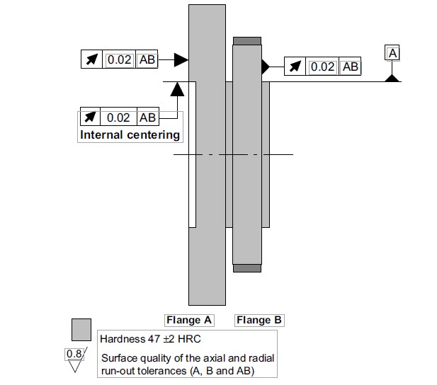
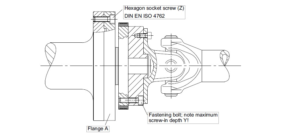
| Measuring range (kN m) | Fastening bolts (Z)1) | Fastening bolts property class | Prescribed tightening moment (N m) | ||||||||||||||||||
| 15/20/25 | M18 | 10.9 | 400 | ||||||||||||||||||
| 30/40/50 | M20 | 560 | |||||||||||||||||||
| 60/70/80 | M22 | 760 | |||||||||||||||||||

HBM 扭矩传感器一直在业界享有盛誉。从1958 年开始, HBM 扭矩传感器(扭力传感器,转矩传感器)一直是行业标准,广泛应用于发动机和零部件测试台架,生产监控和实验室扭矩标定。
HBM 作为全球首家数字扭矩传感器的制造商,产品包括 扭矩传感器 (扭力传感器,转矩传感器), 以及用来测量反作用力的 非转动式 扭矩传感器 (扭力传感器)以及用于扭矩传感器 (扭力传感器) 的各种联轴器 和测量仪表。HBM 拥有 滑环和非接触式信号传输 专利技术,额定测量范围从 0.1 N·m 到 2 MN·m, 额定转速最大到40,000 rpm。
HBM 扭矩传感器一直在业界享有盛誉。从1958 年开始, HBM 扭矩传感器(扭力传感器,转矩传感器)一直是行业标准,广泛应用于发动机和零部件测试台架,生产监控和实验室扭矩标定。
DKD (德国校准服务机构) 的首家标定实验室 1977 在 HBM 成立。1990年7月13日,HBM 被 DKD 授予进行扭矩标定,多年以来, HBM 一直是德国唯一一家可进行 扭矩标定 服务的实验室,并负责制定国家标准.
T12,T40FM,T40,T40B 是新一代数字扭矩传感器。其采用特殊模数转化方法,不仅带有错误识别功能,对电磁环境不敏感,并且具有更高的采样率和更高的精度。
下面这些产品,一样很精彩哟!
产品繁多,总有一款适合你,更可来图来样定制生产,选型!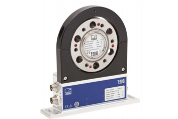
T40B 以高精度、再现性和鲁棒性而著称,非常适合用于静态和动态扭矩测量。包括滞后和高温稳定性,扭矩传感器具有 0.03% 的线性精度。可内置磁学转速测量...
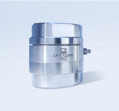
在工厂,CFTplus系列压电力传感器已进行了三个量程段 (1%, 10%和100%)的校准,因此安装后可立即使用,无需进行现场校准。 一般来说,压电原理传感器的...
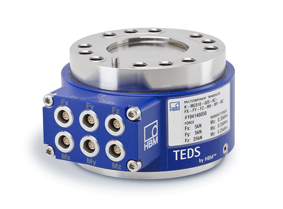
沿不同轴同步测量力和扭矩。3维力传感器! 来自 HBM 的 MCS10 多分量传感器能够同步测量沿三个轴或坐标的力 (Fx, Fy, Fz)。 六分量传感器...

T12HT 扭矩传感器,适用于高达1.5 MN·m 极高扭矩测量 T12HT 扭矩传感器专门针对大扭矩应用设计,高精度,并可大幅提高生产力和效率。其采用无线供电,无线...
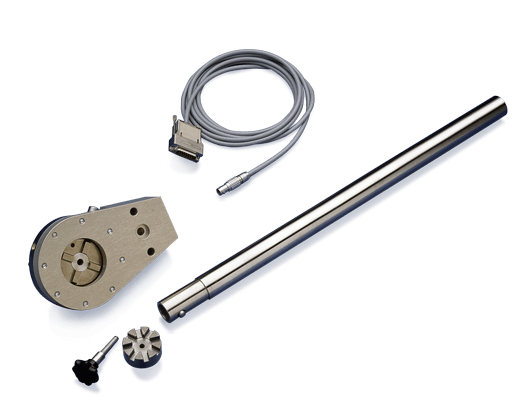
TTS 扭矩扳手 是用来检查和标定扭矩设备.其符合标定的所有要求(DKD-R 3-8 中所描述). 产品描述 由于扭矩扳手会产生特殊扭矩, 因此 TTS 弯矩的极限阻值...
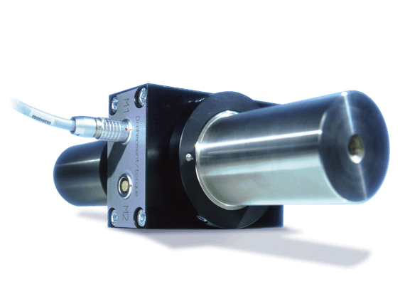
TN 扭矩传感器 是一种非转动传感器,专门用于传感器标准 或作为实验室的比对传感器 其有极高的极高的精度和稳定性. TN 扭矩传感器经常作为国家计量院的...
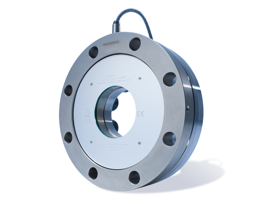
TB1A 扭矩比对测量盘采用HBM的专利技术-剪应力扭矩测量 采用轴向剪应力臂的测量体有很小的尺寸和具有很高的刚性,可以抵御弯矩等其他负载。 简单,...
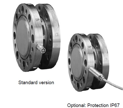
TB2 比对扭矩传感器具有非极高的精度,其带有 DKD标定证书,按照 DIN 51309 或 EA 10-14标准精度等级达到 0.05。标准要求在 40% 到 100% 的额定量程范围...
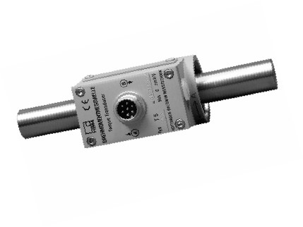
t5 扭矩(扭力/转矩)传感器(特点) 任何旋转方向扭矩的测量 标称扭矩10 NV/m, 20 NV/m, 50 NV/m, 100 NV/m, 200 NV/m 无滑动摩擦接头的圆柱轴...

T4A 扭矩传感器主要用于保证扭矩质量符合国家标准而进行的追溯性测量。 T4A 扭矩传感器的连接通过手动扳手或电动扳手来进行,而不能用气动扳手。 ...
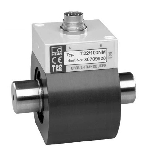
T22 扭矩传感器: 扭矩测量最高达 1 kNm 基于应变的 T22 扭矩传感器采用非接触式传输技术,量程从 0-0.5 Nm 最大到 0-1 kNm。结构紧凑,适合旋转和非旋...

T21WN 扭矩传感器: 扭矩测量最高到 200 Nm 基于应变的 T21WN 扭矩传感器采用非接触式方式进行信号传输和供电。适用于非旋转和旋转部件的较低扭矩静态...

T10F 扭矩传感器: 额定扭矩从 50 N·m 到 10 kN·m 其非常紧凑的设计占有非常小的空间。高侧向的防护允许连接轴直接与法兰连接,无须其它支撑轴,并且可...
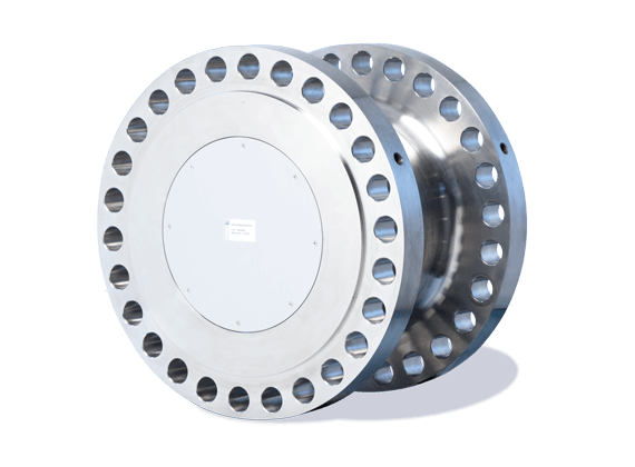
用于确定负载信号的T40MAR认证传感器 高精度 T40MAR 扭矩传感器可以从船舶发动机中获取负载信号,从而可以更好地控制它们。负载信号测定可通过传动系...
T40FH 扭矩传感器: 极高扭矩测量 T40FH 扭矩传感器是 极高扭矩测量 第一选择 - 通过极高扭矩测量提高效率和生产力,而无需其他昂贵设备。 旋转型T4...













以质量求生存,以信誉求发展,满足合同规定及潜在需求!

全国咨询热线
157-6785-5089